Bending Test Diagram

Schematic Diagram Of The Three Point Bending Test Set Up Download Scientific Diagram
Analysis Of Bending Test Technique For Osteosynthesis Titanium Plate Kne Engineering
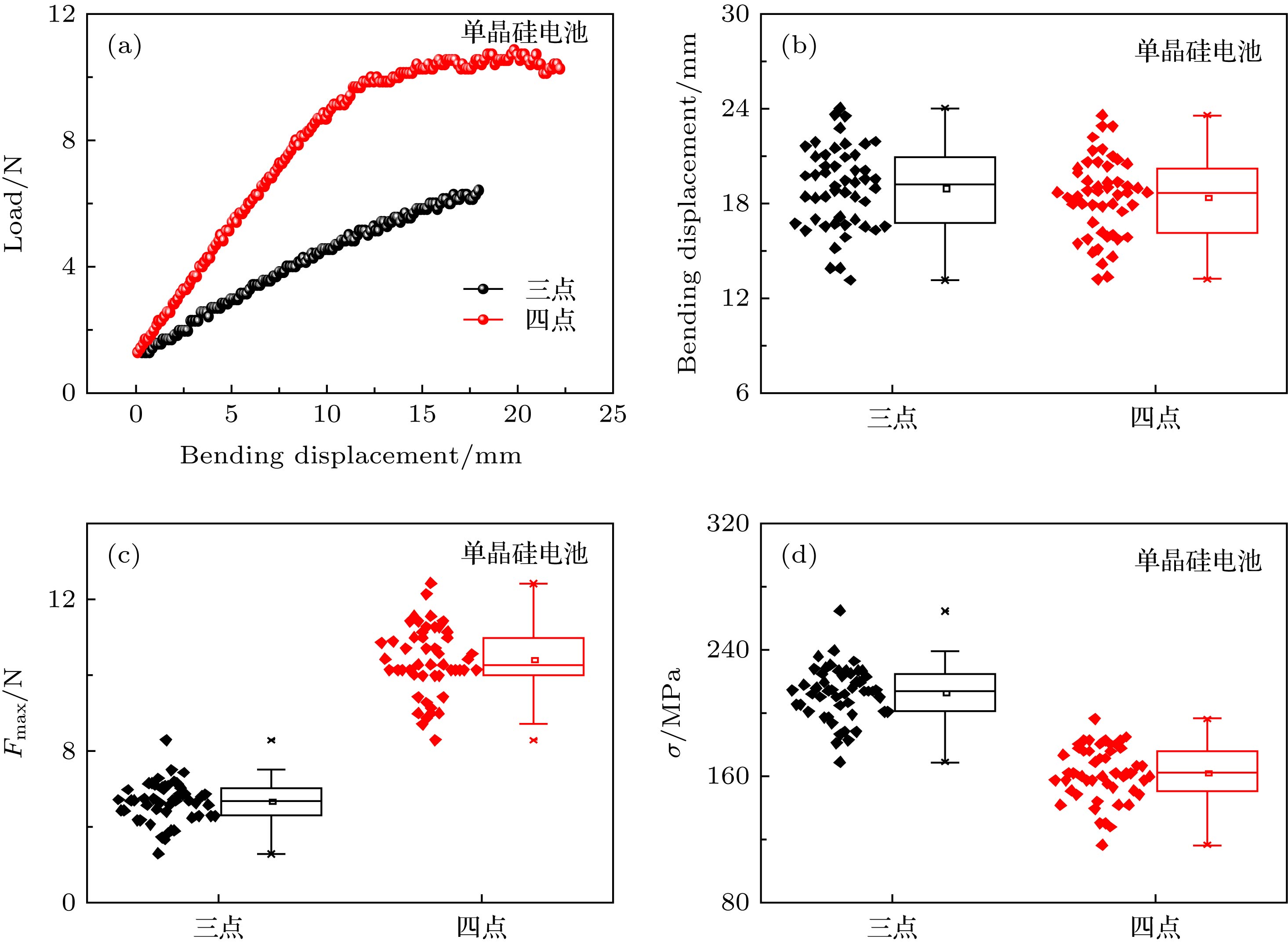
Three Point And Four Point Mechanical Bending Test Modeling And Application In Solar Cells

Comparison Between Three Point And Four Point Flexural Tests To Determine Wood Strength Of Eucalyptus Specimens
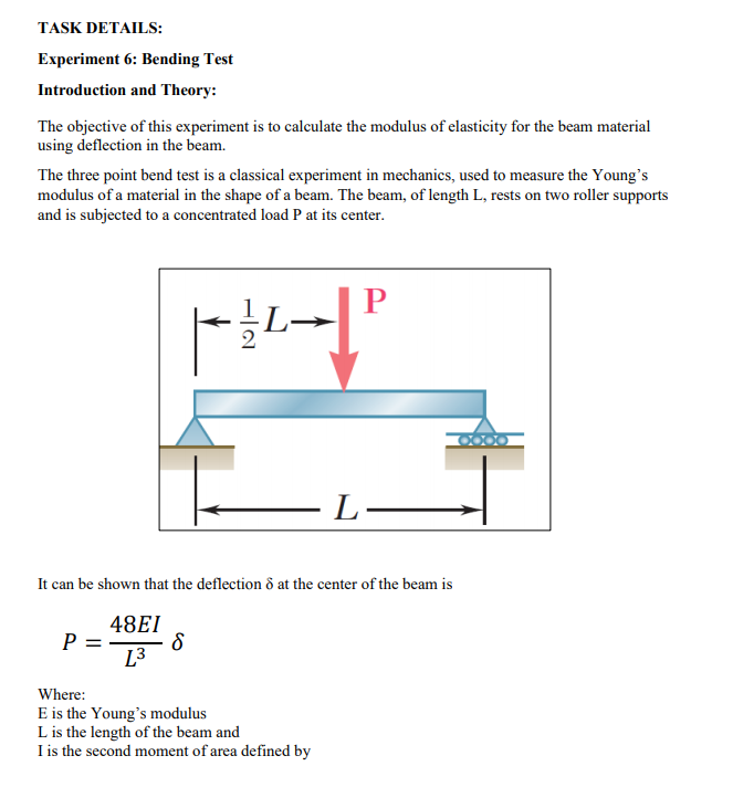
Solved Task Details Experiment 6 Bending Test Introduct Chegg Com

View Image
Jan 19,21 Bending Moment And Shear Force Diagram MCQ Test 2 30 Questions MCQ Test has questions of Mechanical Engineering preparation This test is Rated positive by 86% students preparing for Mechanical EngineeringThis MCQ test is related to Mechanical Engineering syllabus, prepared by Mechanical Engineering teachers.
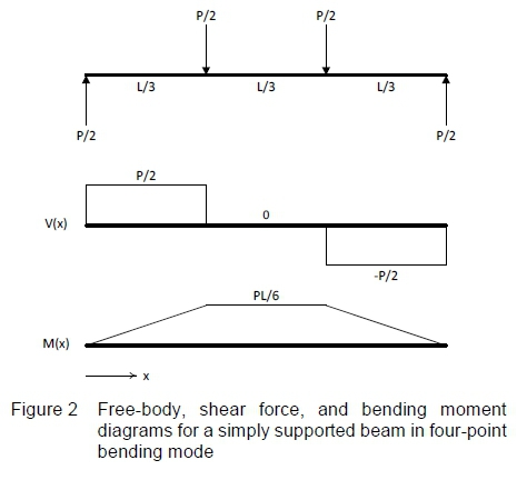
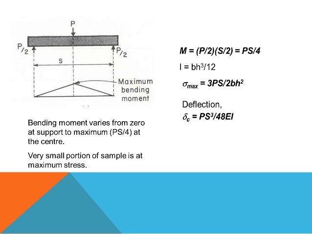
Bending test diagram. The bending moment, M, along the length of the beam can be determined from the moment diagram The bending moment at any location along the beam can then be used to calculate the bending stress over the beam's cross section at that location The bending moment varies over the height of the cross section according to the flexure formula below. Bending stresses are produce in a beam when an external force is applied on the beam and produce deflection in the beam Bending stresses main depends on the shape of beam, length of beam and magnitude of the force applied on the beam In order to calculate the bending stresses in the beam following formula can be used. M B = 0;.
To draw the bending moment diagram the distances are taken on xaxis and bending moment values on yaxis. 4 API Modified Goodman Diagram 7 5 Wohler's test Arrangement and SN Diagram 9 6 Typical RotatingBending Test Arrangement 11 7 Typical RotatingBending Test Machine 12 8 Several Constant Amplitude stressTime Pattems 23 9 Typical Dynamometer Card 26 10 MTS Fatigue Testing Machine 32 11 Closed Loop Control Diagram 34 12. A bending test, also known as a bend test, is used to determine the strength of a material by applying force to the item in question and seeing how it reacts under pressure Typically the bend test measures ductility, the ability of a material to change form under pressure and keep that form permanently In certain cases the bending test can.
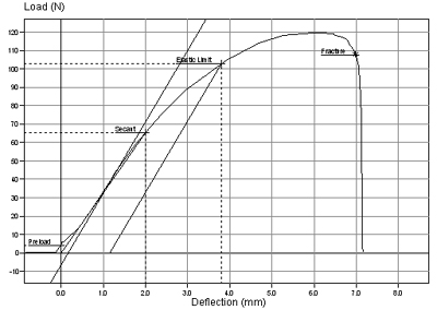
Jan 06,21 Test Bending Moment Diagram 15 Questions MCQ Test has questions of Mechanical Engineering preparation This test is Rated positive by 93% students preparing for Mechanical EngineeringThis MCQ test is related to Mechanical Engineering syllabus, prepared by Mechanical Engineering teachers. There is an external moment on the section So a bending moment will be induced in section, in order to balance the external moment Since value of external moment is F into x, bending moment will vary linearly Section BC Between B and C effect of force F 2 also comes So shear force becomes, F 1 plus F 2 And in bending moment effect of F 2. The threepoint bending test provides the loaddeflection curve, which can be used to obtain the corresponding stresscrack width curve From the test, the diagram of the applied force (F) versus the deformation can be produced, in which the deformation is expressed in terms of crack mouth opening (CMOD), as shown in Figure3.
C53 Shear Force and Bending Moment Diagrams You probably can tell from the examples previously that the shear force SF and bending moment BM varies along the beam, due to the varying loads From an engineer’s point of view, you would want to find out where the maximum SF or BM is – ie the weakest part of the beam This is so that you can design to ensure that it’s safe!. A simple instruction on how to calculate the bending moment diagram of a simply supported beam, both by hand and by SkyCiv Beam Calculator. The firstorder bending frequency f 1 of the free beam test piece was calculated using formula (1), and the test block diagram and the tested spectrum are shown in Figs 1 and 2, respectively Fig 1 Dynamic test block diagram of elastic modulus of lumber under free beam conditions.
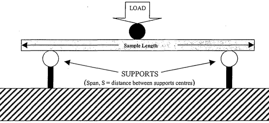
The most common test is tension test for metals, to obtain the stressstrain diagram of materials (compression test are most used for rock and concrete) cylindrical specimen are used ASTM standard specimen for tension test (round bar) d = 05 in (127 mm) GL = in (50 mm) when the specimen is mounted on a testing system (MTS, Instron etc),. Schematic diagram of a threepoint bending test Dark lines depict the undeformed bone, and the lighter lines the deformed (displaced) bone The bone is place on two support third (loading) point applies a load at the middiaphysis For femur testing (as shown) we put the anterior surface. A simple instruction on how to calculate the bending moment diagram of a simply supported beam, both by hand and by SkyCiv Beam Calculator.
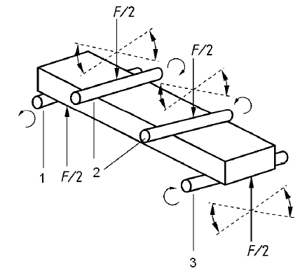
Cantilever Bending Test Machine Load amplitude changes with specimen cyclic hardening or softening and decreases as cracks in the specimen nucleate and grow The eccentric crank test machines do have an advantage over the rotating bending test machines in that the mean deflection, and hence the initial mean stress, can be varied. Analysis of four point bending The values obtained in this example are dependent on the initial spacing of the applied loads Also, the shear and moment dia. Learn about bending/flexural testing and the materials testing solutions we provide for bending/flexural testing.
Test setup In the bending flexural test, a specimen is loaded under uniaxial bending stress (tension and compression) in order to obtain information on the bending behaviour of materialsEspecially brittle materials such as hard metals, tool steels and grey cast iron are tested in flexural tests In such a bending test flexural strength, deflection at fracture and modulus of elasticity, for. Shearforce and bending moment experiment lab report of Shear force and bending moment experiment for concentrated and symmetrical l View more University Multimedia University Course AppliedStatics (eme1016) Uploaded by Chai Hao Academic year 15/16. Jan 06,21 Test Bending Moment Diagram 15 Questions MCQ Test has questions of Mechanical Engineering preparation This test is Rated positive by 93% students preparing for Mechanical EngineeringThis MCQ test is related to Mechanical Engineering syllabus, prepared by Mechanical Engineering teachers.
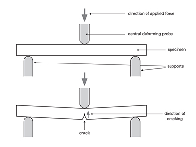
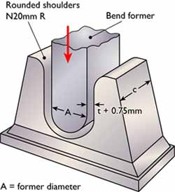
The bend test uses a coupon that is bent in three point bending to a specified angle The outside of the bend is extensively plastically deformed so that any defects in, or embrittlement of, the material will be revealed by the premature failure of the coupon. Bending Moment and Shear Force calculations may take up to 10 seconds to appear and please note you will be directed to a new page with the reactions, shear force diagram and bending moment diagram of the beam. Nickbreak test is a variant intended to test the soundness of a weld From a groove welded test panel, a section of say 50 mm (2") width is removed Two saw cuts are machined before bending, for a depth of about 6 mm (1/4"), at both the width sides of the specimen section, along the whole depth of the weld.
To draw the bending moment diagram the distances are taken on xaxis and bending moment values on yaxis. M D = 66 x 8 x 4 x 6 = 528 480 = 48 kNm;. Fig2 (a) Sample 1 Maximum load = 175 N, Bending strength= 71 X 10 6 N/m 2 3 E XPERIMENTAL P ROCEDURE Three point bending testing is done to understand the Bending Stress, Flexural Stress, and Flexural Strain of the composite materials The 3 point bending test is carried out in an Instron Testing Machine in the department of mechanical.
•)The bending moment diagram is a concave up parabolic curve for positiveω(xand a concave down xparabolic ω() curve for negative Equations (1) and (2) can be rewritten in form the left end to the right end of an integral form, the same segment as followings − =∫ right end left end V right end V left end w(x)dx(3) − =∫. Click here to get more about nature of bending moment diagram due to different loadings M A = 0;. Bending moment often exists in the chord member of a Vierendeel truss The interaction of bending moment in the chord and the web buckling or chord flange yielding was studied by Zhao and Hancock (1991a)The dimensionless loading (P/P f) versus the dimensionless moment (M/M f) is plotted in Figure 68 (a) for β = 10 and in Figure 68 (b) for β = 05The terms P f and M f are the test values.
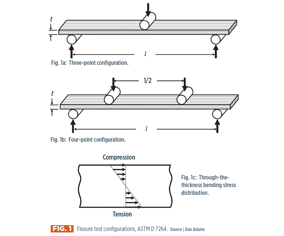
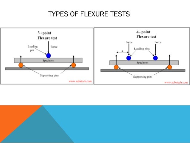
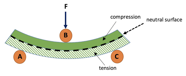
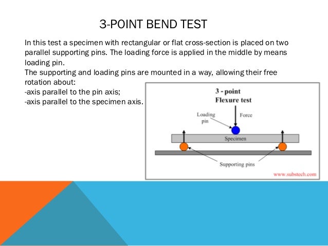
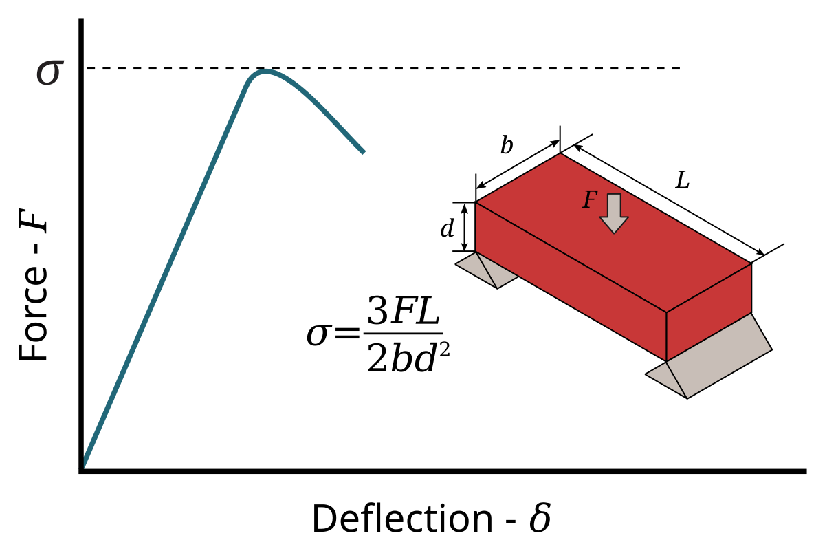
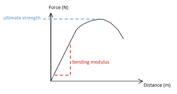
Learn bending with free interactive flashcards Choose from 500 different sets of bending flashcards on Quizlet. Click here to get more about nature of bending moment diagram due to different loadings M A = 0;. 3point bending test It produces its peak stress at the material midpoint and reduced stress elsewhere 4point bending test It produces peak stresses along an extended region of the material hence exposing a larger length of the material The elastic modulus in bending (E) can be extracted from a flexural test.
As the load is increased, the bending moment increases as well For example, at 5N it is 9548N and at 15N it is N The experimental bending moment is close to the theoretical bending moment and this displays that the test was successfully performed. Empirical data from RR Moore fatigue test (Highly standardized and restricted conditions) Rotatingbeam fatiguetesting machine Pure bending (zero traverse shear) N cycles of tensiontocompressiontotension 1750 rpm various. The bending moment, M, along the length of the beam can be determined from the moment diagram The bending moment at any location along the beam can then be used to calculate the bending stress over the beam's cross section at that location The bending moment varies over the height of the cross section according to the flexure formula below.
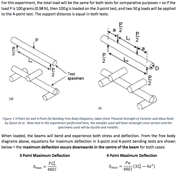
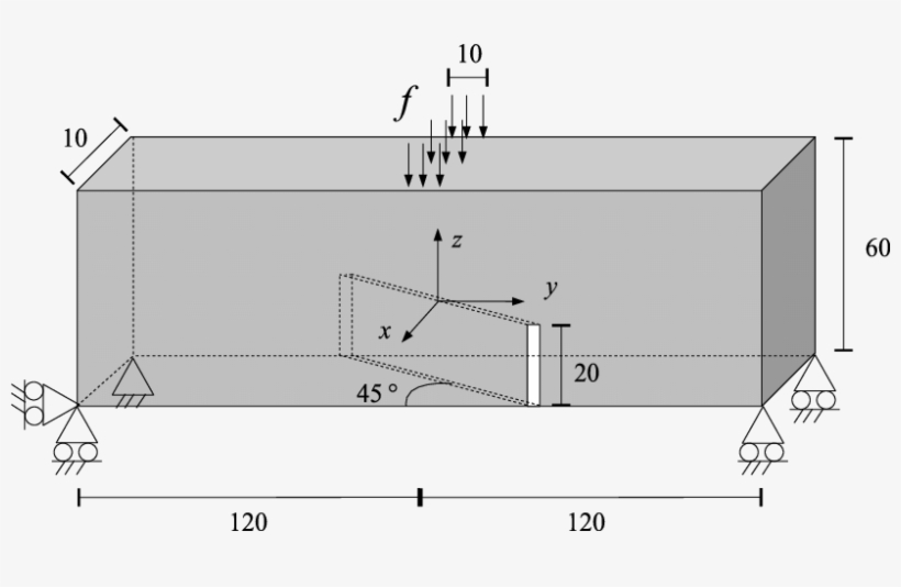
Rotating bending test and reverse bend test A special type of fatigue test is the rotating bending test, where a round specimen is subjected to an alternating bending stress in order to test bending fatigue strength Due to the constant bending moment and rotation, the tensile and compressive stresses produced in the material change permanently. The three point bend test (Figure 1) is a classical experiment in mechanics, used to measuretheYoung’smodulusofamaterialintheshapeofabeam Thebeam,oflength L, rests on two roller supports and is subject to a concentrated load P at its centre Figure 1 Schematic of the three point bend test (top), with graphs of bending moment M, shear Q and deflection w Figure reproduced from. (a) Schematic diagram of the test setup used to determine the openingmode flexural stiffness and strength of the legjunction of a pultruded GFRP equalangle profile specimen (note that the forces f represent the friction acting on the sliding supports);.
Being able to draw shear force diagrams (SFD) and bending moment diagrams (BMD) is a critical skill for any student studying statics, mechanics of materials, or structural engineering There is a long way and a quick way to do them The long way is more comprehensive, and generates expressions for internal shear and internal bending moment in. (b) openingmode test on an equalleg angle (note that there is significant internal. Determined according to an appropriate diagram in Fig5 The moment at midspan of the test beam corresponding to F u is where L = span of the specimen (mm) Assuming a stress distribution as shown in Fig 6, the limit of proportionality f fct,fl can be calculated using the following expression where b = width of the specimen (mm);.
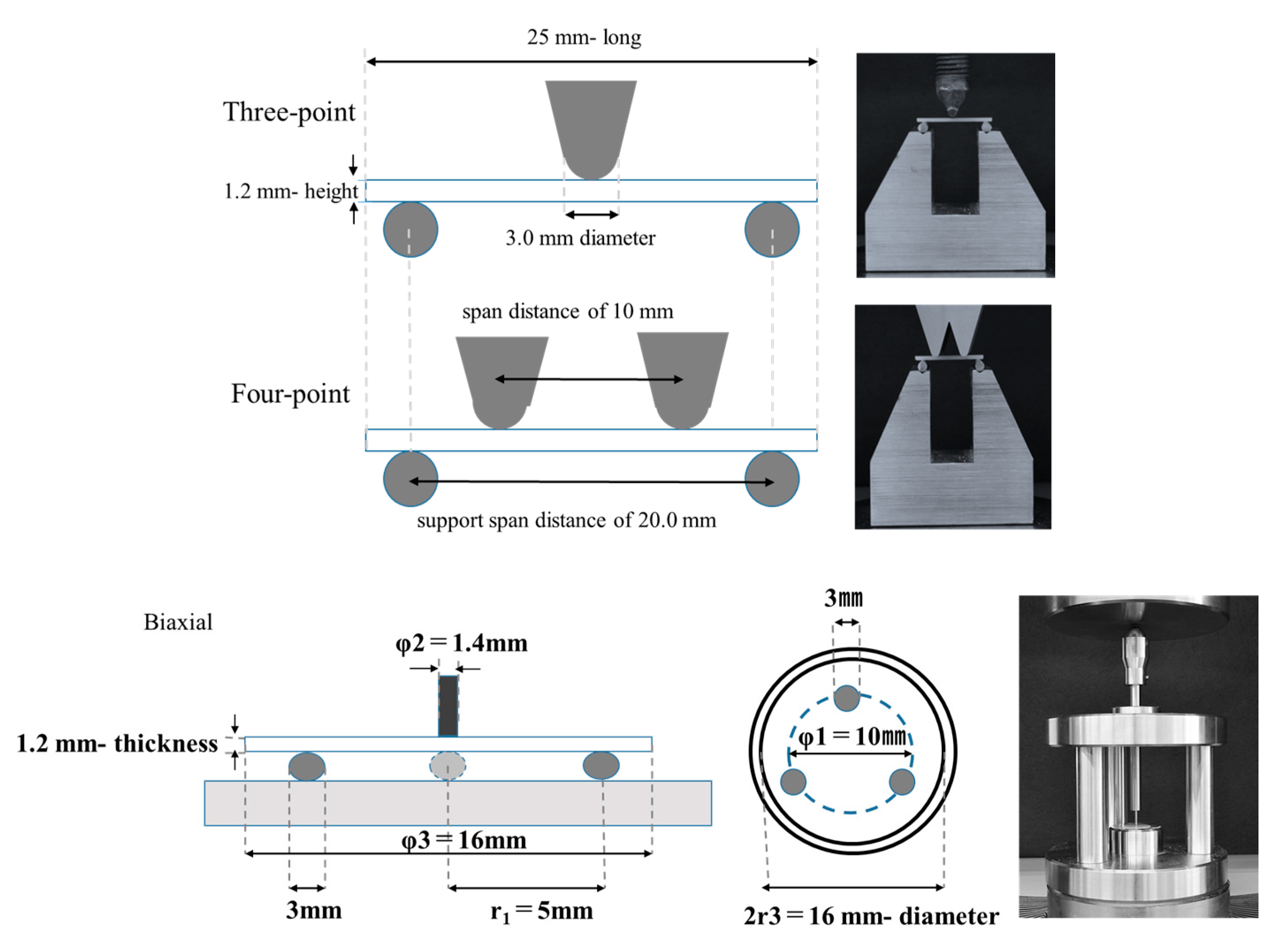
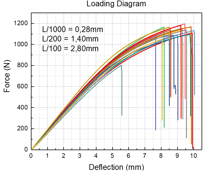
M C = 66 x 4 x 4 x 2 = = 104 kNm;. 💡 The internal bending moment , is the bending moment we represent in a bending moment diagram The bending moment diagram shows how (and therefore stress) varies across a structure If we know the state of longitudinal or normal stress due to bending at a given section in a structure we can work out the corresponding bending moment. Threepoint static bending test according to the code NBR 7190/1997 allows to determine two wood properties modulus of elasticity and conventional value of Strength According to this code, determination of the modulus of elasticity must be through loading cycle occurring between 10% and 50% of the rupture of an estimation sample However, it is usual to perform these cycles using L/0 and L.
These instructions will help you to calculate and draw shear and bending moment diagram, as well as draw the resulting deflection Knowing how to calculate and draw these diagrams are important for any engineer that deals with any type of structure because it is critical to know where large amounts of loads and bending are taking place on a beam so that you can make sure your structure can. The bending moment at the two ends of the simply supported beam and at the free end of a cantilever will be zero Shear force and Bending moment Diagram for a Cantilever beam with a Point load at the free end Shear force and Bending moment Diagram for a Cantilever beam with a Uniformly distributed load. Shear and bending moment diagrams are analytical tools used in conjunction with structural analysis to help perform structural design by determining the value of shear force and bending moment at a given point of a structural element such as a beam These diagrams can be used to easily determine the type, size, and material of a member in a structure so that a given set of loads can be supported without structural failure Another application of shear and moment diagrams is that the deflection o.
M C = 66 x 4 x 4 x 2 = = 104 kNm;. Calculate the reactions at the supports of a beam, automatically plot the Bending Moment, Shear Force and Axial Force Diagrams BEAMGURUCOM Bending moment diagram (BMD) Shear force diagram (SFD) Axial force diagram Invert Diagram of Moment (BMD) Moment is positive, when tension at the bottom of the beam. Jan 19,21 Bending Moment And Shear Force Diagram MCQ Test 2 30 Questions MCQ Test has questions of Mechanical Engineering preparation This test is Rated positive by 86% students preparing for Mechanical EngineeringThis MCQ test is related to Mechanical Engineering syllabus, prepared by Mechanical Engineering teachers.
Procedure for determining shear force and bending moment Determine the reactions using the equilibrium conditions of the overall structure Cut the beam at the cross section at which shear force and bending moment are to be determined Draw a freebody diagram Set up equilibrium equations of the FBD to determine shear force and bending moment. 4 API Modified Goodman Diagram 7 5 Wohler's test Arrangement and SN Diagram 9 6 Typical RotatingBending Test Arrangement 11 7 Typical RotatingBending Test Machine 12 8 Several Constant Amplitude stressTime Pattems 23 9 Typical Dynamometer Card 26 10 MTS Fatigue Testing Machine 32 11 Closed Loop Control Diagram 34 12. 0000 Introduction to 3 Point bending0228 Explanation result graphs0535 Setting up simulation file0606 Defining the material from Test data (Multi.
Bending stiffness of a beam can be determined from a forcedisplacement diagram obtained during a threepoint bending test If the beam has a uniform crosssection and elastic properties along, the bending stiffness to a concentrated force applied in the midspan can be calculated as k= 48EI L3 e (1) where L. This is an excellent course and it truly gives you a deep insight into the way a structure behaves on the application of external loads and you develop a great understanding of the Shear force and Bending moment diagrams which essentially are the tools used to analyse a structure completely. The bending test shall cover both cord and strain relief The test is over when the first conductor is broken, the resistance of the conductor increases more than % or exceeds the value specified in the cord/cable drawing Engineering Testing Flow Chart START (15 Samples) No Yes END.
The Three Point Bend Test 1 Beam theory The three point bend test (Figure 1) is a classical experiment in mechanics, used to measuretheYoung. Threepoint static bending test according to the code NBR 7190/1997 allows to determine two wood properties modulus of elasticity and conventional value of Strength According to this code, determination of the modulus of elasticity must be through loading cycle occurring between 10% and 50% of the rupture of an estimation sample However, it is usual to perform these cycles using L/0 and L. M D = 66 x 8 x 4 x 6 = 528 480 = 48 kNm;.
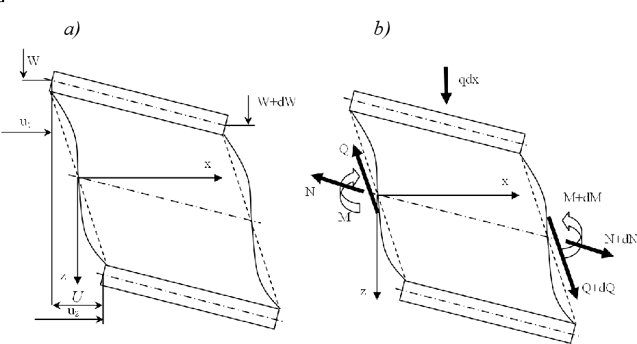
FOUR POINT BENDING TEST 1 Bending Theory for a Rectangular Beam 11 General Theory The deflections due to shear V s and due to bending V b of a rectangular beam, which is vertical loaded along the beam by a force Q(x,t) are governed by two differential equations (assuming homogenous material). A bending test, also known as a bend test, is used to determine the strength of a material by applying force to the item in question and seeing how it reacts under pressure Typically the bend test measures ductility , the ability of a material to change form under pressure and keep that form permanently. Being able to draw shear force diagrams (SFD) and bending moment diagrams (BMD) is a critical skill for any student studying statics, mechanics of materials, or structural engineering There is a long way and a quick way to do them The long way is more comprehensive, and generates expressions for internal shear and internal bending moment in.
M B = 0;. TecQuipment Bending Moment in a Beam Student Guide Figure 2 Bending moment of a beam experiment in the structures frame Steps 1 to 4 of the following instructions may already have been completed for you 1 Place an assembled Test Frame (refer to the separate instructions supplied with the Test Frame if necessary) on a workbench.

Schematic Diagram For The Three Point Bending For Flexural Testing Download Scientific Diagram

Astm C1399 Four Point Bending Fixture For Fiber Reinforced Concrete Gc1399 902
Texture Analysis Professionals Blog Physical Property Measurement Fracture Testing In Bending

Comparison Between Three Point And Four Point Flexural Tests To Determine Wood Strength Of Eucalyptus Specimens
Q Tbn And9gcrymtbaknznh6ldjnumlub7aaw6o9psjg7cyj6pn6hteiidvixi Usqp Cau

Bending Flexural Test Tec Science

3 Point Bend Testing Bruker Umt Mechanical Tester Bruker

Flexural Testing An Overview Sciencedirect Topics
3 Bending Test

Schematic Of The Three Point Bend Test With Graphs Of Bending Moment Download Scientific Diagram

Evaluation Of A Four Point Bending Test Method For Interface Shear Transfer In Concrete Members Practice Periodical On Structural Design And Construction Vol 22 No 4
4 Point Bending Test The Flexural Strength Of Mort Chegg Com
Can Flexure Testing Provide Estimates Of Composite Strength Properties Compositesworld

Schematic Diagrams Of A Three Point Bending Test And B Photo Stress Download Scientific Diagram
Www Forcegauge Net Wp Content Uploads Bt E Pdf
3 Point Bend Test
Materials Free Full Text Reliability Of Different Bending Test Methods For Dental Press Ceramics

Flexural Strength Testing

Three Point Bending Test 8 Download Scientific Diagram

Schematic Representation Of The Set Up For The Three Point Bending Test Download Scientific Diagram
Bending Flexural Testing

Comparison Of Results Obtained By Static 3 And 4 Point Bending And Flexural Vibration Tests On Solid Wood Mdf And 5 Plywood In Holzforschung Volume 67 Issue 8 13

Objectives Template

Bending Tests An Overview Sciencedirect Topics

Three Point Flexural Test Wikipedia

Four Point Bending Test Of Determining Stress Strain Curves Asymmetric Between Tension And Compression Springerlink

Schematic Diagram Of The Three Point Bending Test Set Up Download Scientific Diagram
Texture Analysis Professionals Blog Three Point Bend Testing Using A Texture Analyser Calculating Fundamental Parameters
Q Tbn And9gcq1ccl43zipdk9avvfjwplqzake3thklaucae2w6xtpgwu5kq7c Usqp Cau
Static Bending Loading Diagram In Wood

Out Of Plane Two Way Bending Test Tud Comp 7

Flexural Strength Testing

Diagram Of Three Point Bending Test Setup The Three Point Bending Jig Download Scientific Diagram
High Velocity 3 Point Bending Test Using An Impact Tower

Bending Test Shubbakom

Four Point Bending Test Of Determining Stress Strain Curves Asymmetric Between Tension And Compression Springerlink
3 Point Bend Test

Bending Tests An Overview Sciencedirect Topics
Scielo Conicyt Cl Pdf Maderas Vn3 0718 221x Maderas Pdf

A Simplified Diagram Of The 3 Point Bending Test Download Scientific Diagram
Solved Stress Calulations For 3 Point And 4 Point Bend Te Chegg Com
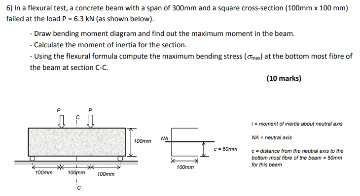
Solved 6 In A Flexural Test A Concrete Beam With A Spa
Pdf Experimental And Numerical Three Point Bending Test For Sandwich Beams Semantic Scholar
Pdf Experimental And Numerical Three Point Bending Test For Sandwich Beams Semantic Scholar
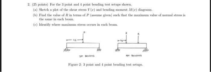
Solved For The 3 Point And 4 Point Bending Test Setups Sh Chegg Com
Products
Bend Testing Twi

Objectives Template
Three Point And Four Point Mechanical Bending Test Modeling And Application In Solar Cells
Http Homepages Cae Wisc Edu Lakes Bme315bonedetails Pdf
Cpb Us W2 Wpmucdn Com Sites Wustl Edu Dist F 19 Files 19 05 Understanding 3pt Bending Outcomes Pdf

Diagram Of Three Point Bending Test Setup The Three Point Bending Jig Download Scientific Diagram

Schematic Diagram Of The Standard 3 Point Bend Test Download Scientific Diagram
Mechanical Behaviors Of Enamel Dentin And Dental Restorative Materials By Three Point Bending Test

Ovalization Restraint In Four Point Bending Tests Of Tubes Journal Of Engineering Mechanics Vol 145 No 3

Rotating Bending Test An Overview Sciencedirect Topics

Bendability Test Of Stentgrafts Jfe Techno Research Corporation

Flexural Or Bend Testing Touchstone Testing Lab Llc
Q Tbn And9gcr95ba77umckxf2 Uwxbllik4apmjak0sfbuwcay0htr5lflowt Usqp Cau

Three Point Bending Test An Overview Sciencedirect Topics
Flexural Strength Wikipedia

Displacement Errors In Materials Testing
Static Bending Loading Diagram In Wood

Texture Analysis Professionals Blog Three Point Bend Testing Using A Texture Analyser Calculating Fundamental Parameters
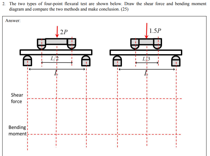
Solved 2 The Two Types Of Four Point Flexural Test Are S Chegg Com
Q Tbn And9gcs8evslw4psdj Tnnakiws Jdlyjvxphptr7r2y5vultwp8j2fw Usqp Cau

Bending Flexural Test Tec Science

What Is Bend Testing Instron

Cyclic 4 Point Bending Test Testresources

Virtual Labs
A Schematic View Of A Bend Test A And An Overview Procedure Of The Download Scientific Diagram
3 Bending Test

Schematic Of Flexure Tests 3 Point And 4 Point Bending Test 36 Download Scientific Diagram
Kit Research Ame Research Ame Mechanical Testing Compression And Four Point Bending Test
Http Mi Eng Cam Ac Uk Ialego Bender Files Bend Theory Pdf

What Is Bend Testing Instron

Inverse Characterisation Of Gradient Distribution Of The Modulus Of Bamboo Using A Four Point Bending Test In Holzforschung Ahead Of Print

Schematic Of Three Point Bending Test A Initial Shape And Download Scientific Diagram
Products
Four Point Bending Fatigue Test Specimen Design By Fea

Three Point Bending Test At Extremely High Temperature Enhanced By Real Time Observation And Measurement Sciencedirect

A Schematic Illustration Of The Three Point Bending Test Download Scientific Diagram

Flexural Or Bending Test Lab Report Deformation Engineering Strength Of Materials
Eprintspublications Npl Co Uk 1564 1 Mgpg7 Pdf
Scielo Conicyt Cl Pdf Maderas Vn3 0718 221x Maderas Pdf

Out Of Plane Two Way Bending Test Tud Comp 11

Virtual Labs
Mechanical Behaviors Of Enamel Dentin And Dental Restorative Materials By Three Point Bending Test

Pdf Experimental And Numerical Three Point Bending Test For Sandwich Beams Semantic Scholar

Bending Test Diagram Sukkahville 13 Parametric Design Generative Architecture
3 Point Bend Solves Iphone6 Bending Problem

Three Point And Four Point Mechanical Bending Test Modeling And Application In Solar Cells

Three Point Bending Test Schematic Test Setup Download Scientific Diagram
Texture Analysis Professionals Blog Three Point Bend Testing Using A Texture Analyser Calculating Fundamental Parameters

Three Point Bending Youtube

Schematic Description Of Three Point Bending Test Device Download Scientific Diagram
Three Point Bending Test With An Initial Skew Crack Diagram 819x454 Png Download Pngkit
3 Point Bend Test


